Husqvarna 18 ProFlex User Manual
Browse online or download User Manual for Gardening equipment Husqvarna 18 ProFlex. Husqvarna 18 ProFlex User Manual
- Page / 48
- Table of contents
- BOOKMARKS
Rated. / 5. Based on customer reviews
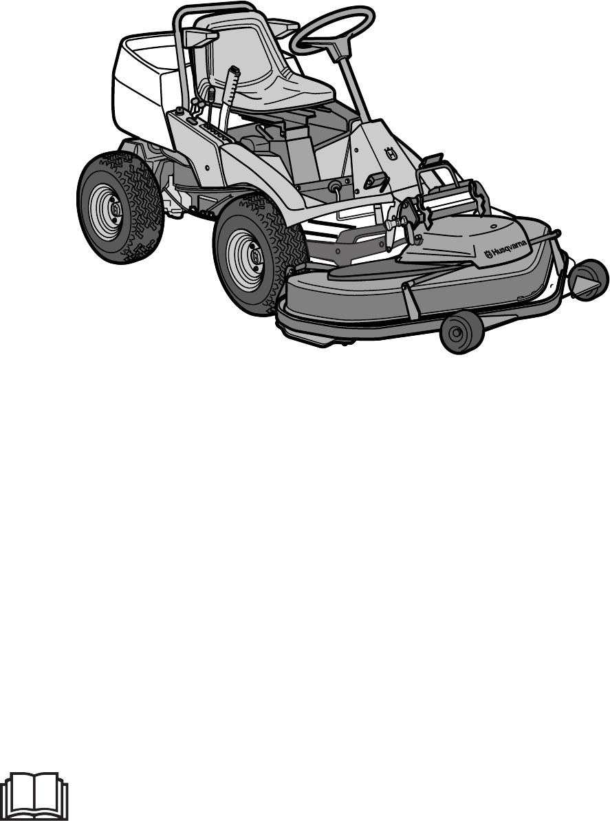
Please read these instructions carefully and make sure
you understand them before using the machine.
101 89 84-26
Operator´s manual
Rider 18 ProFlex
Rider 20 ProFlex
- Rider 18 ProFlex 1
- Rider 20 ProFlex 1
- Svenska – 31 2
- Operator’s Manual for 3
- CONTENTS 3
- EXPLANATION OF SYMBOLS 6
- SAFETY INSTRUCTIONS 10
- PRESENTATION 11
- Before starting 15
- Starting the engine 15
- Driving the machine 16
- Cutting tips 17
- Disengage lever 18
- Stopping the engine 18
- MAINTENANCE 19
- TROUBLE SHOOTING SCHEDULE 41
- Winter storage 42
- WIRING DIAGRAM 43
- TECHNICAL DATA 44
- ´*2§J¶6)¨ 46
- English – 45 47
Summary of Contents
Page 1 - Rider 20 ProFlex
Please read these instructions carefully and make sureyou understand them before using the machine.101 89 84-26Operator´s manualRider 18 ProFlexRider
Page 2 - Svenska – 31
8 – Englishmachine, and leave space for the fuel to expandsince the heat from the engine and hot sun cancause the fuel to run over.• Avoid overfilling
Page 3 - CONTENTS
English – 9PresentationCongratulations on choosing an excellent qualityproduct, Rider ProFlex. These instructions describetwo models, Rider 18 ProFlex
Page 4
10 – EnglishThrottle controlThe throttle control regulates the engine speed, andthereby also the rotation speed of the blades.To increase or reduce th
Page 5
English – 11Cutting unitRider 18 ProFlex and Rider 20 ProFlex can beequipped with numerous attachments.The BioClip unit finely cuts the lawn by cuttin
Page 6 - EXPLANATION OF SYMBOLS
12 – EnglishPRESENTATION!WARNING!Petrol is highly inflammable. Exercisecare and refuel outdoors (see safetyinstructions).FuellingThe engine should be
Page 7
English – 13Before starting• Read the safety instructions and information onthe location and function of the controls beforestarting (see pages 5–12).
Page 8
14 – English5. When the engine starts release the ignition keyimmediately back to neutral position.IMPORTANT INFORMATIONDo not run the starter for mor
Page 9
English – 153. Select the required cutting height (1–7) with thecutting height lever.4. Push in the lock button on the lift lever and lowerdown the cu
Page 10 - SAFETY INSTRUCTIONS
16 – EnglishStopping the enginePreferably allow the engine to idle for a minute toobtain normal working temperature before stoppingit if it has been w
Page 11 - PRESENTATION
English – 17Maintenance scheduleThe following is a list of the maintenance which should be conducted on the machine. For the items whichare not descri
Page 12
Svenska – 31Sve-5 225/232/235 Bruk 97-11-25, 08.4631
Page 13
18 – EnglishDismantling of the machine hoodsEngine hoodRelease the two rubber straps on the rear edge ofthe engine hood and lift off the hood.NoseLoos
Page 14
English – 19MAINTENANCEChecking of the fuel pump’s air filterCheck regularly that the fuel pump’s air filter is freefrom dirt.The filter can when nece
Page 15 - Starting the engine
20 – EnglishCheck the transmission’s air intakeCheck that the transmission’s air intake in notblocked.Check the transmission’s oil level1. Check the t
Page 16 - Driving the machine
English – 21Checking and adjustment of thesteering wiresThe steering is controlled by means of wires.These can in time become slack, which implies tha
Page 17 - Cutting tips
22 – EnglishAdjusting the brakesThe brakes are adjusted as follows:1. Loosen the lock nuts (A).2. Adjust the wire using the adjuster screw (B)until th
Page 18 - Stopping the engine
English – 23Replacing the air filterIf the engine seems to lack power or does not runsmoothly this may be because the air filter isclogged.It is there
Page 19 - MAINTENANCE
24 – EnglishMAINTENANCE1. Fit the unit in the attachment frame’s outerhooks.The parts of the cutting unitA cutting unit with a rear ejector has been u
Page 20
English – 255. Fit the height setting arm’s rear bracket whenfitting the attachment. Off-load the arm bypulling the front of the frame upwards.6. Remo
Page 21
26 – English1. The cutting unit should be lowered on a levelsurface.2. The height setting lever should be set for thelowest cutting height.Parallelism
Page 22
English – 27MAINTENANCE2. Adjust the unit’s ground pressure by screwing inor out the adjusting screws located behind thefront wheels on both sides.The
Page 23
English – 1Operator’s Manual forRider 18 ProFlex and Rider 20 ProFlexCONTENTSIMPORTANT INFORMATIONRead through these instructions carefullyso that you
Page 24
28 – EnglishMAINTENANCEService position for the cutting unitThe cutting unit can be set in a service position toprovide good access for cleaning, serv
Page 25
English – 29Dismantling the cutting unit1. Place the Rider on a level surface.2. Apply the brakes by pressing down the pedaland lock using the pushbut
Page 26
30 – English9. Loosen the height setting arm by moving therear section upwards. When dismantling thecutting unit, off-load the arm by pulling theframe
Page 27
English – 31MAINTENANCEDismantling the beltStarting point when dismantling the belt:• No unit attached to the Rider.• The front of the belt is hung ar
Page 28
32 – EnglishAssembling the belt1. Position the belt from the front and let the frontend of the belt hang around the hook guard’shandle.2. Fit the belt
Page 29
English – 33MAINTENANCEReplacing the cutting unit’s beltsBelt replacement on the BioClip unitTwo transmission belts that synchronise the rota-tion of
Page 30
34 – EnglishMAINTENANCE2. Loosen the spring that tensions the V-belt andpry off the belt.To fit a new belt, follow the instructions above inthe revers
Page 31
English – 35MAINTENANCEChanging the oilThe oil should be changed for the first time after 8hours of running time. Thereafter it should bechanged every
Page 32
36 – EnglishReplacement of the oil filter1. Dismantle the engine hood as described onpage 18.2. Drain off the engine oil according to the workdescript
Page 33
English – 37Checking and adjustment of the throttlewireCheck that the engine responds to the throttlecontrol and that the correct engine speed isachie
Page 34
2 – EnglishSAFETY INSTRUCTIONS1. Safety rules for USASafe operation practices for ride-on mowersIMPORTANT!This cutting machine is capable of amputatin
Page 35
38 – EnglishChecking the tyre pressureThe tyre pressure should be 60 kPa (0.6 kp/cm2)all round.To improve driving the pressure on the rear tyrescan be
Page 36
English – 39TROUBLE SHOOTING SCHEDULEProblem ProcedureEngine will not start. • Fuel tank empty.• Plugs defective.• Plug connections defective.• Dirt i
Page 37
40 – EnglishWinter storageSTORAGETo put the machine in order for storage follow theseinstructions:1. Carefully clean the machine, especially underthe
Page 38
English – 41WIRING DIAGRAM1. Brake switch, hydrostat2. Microswitch, cutting unit3. Microswitch, seat4. Ignition lock5. Counter6. Start relay7.
Page 39
42 – EnglishTECHNICAL DATAWhen the service life of this product has been served and it is no longer used it should be returned tothe dealer or to an a
Page 40
English – 43Cutting unitTECHNICAL DATARear ejector 120 BioClip 103Cutting width 1200 mm 1030 mmCutting heights 7 settings, 40-100 mm 7 settings, 45-10
Page 41 - TROUBLE SHOOTING SCHEDULE
44 – English´*2§J¶6)¨NOTES
Page 42 - Winter storage
English – 45
Page 43 - WIRING DIAGRAM
´*2§J¶6)¨1998W51
Page 44 - TECHNICAL DATA
English – 3SAFETY INSTRUCTIONSIV. Service1. Use extra care in handling gasoline and otherfuels. They are flammable and vapours areexplosive.a) Use onl
Page 45
4 – EnglishThese symbols are on the machine and in the instructions.Study them carefully so that you know what they mean.Read the instructions.Reverse
Page 46 - ´*2§J¶6)¨
English – 5These instructions are for your safety. Read them carefully.SAFETY INSTRUCTIONSThis symbol implies that important safety rules are applicab
Page 47 - English – 45
6 – English• Watch out for traffic when working close to aroad, or crossing one.• Be careful when rounding a fixed object so thatthe blades do not hit
Page 48
English – 7• Do not cut close to edges, ditches or banks. Themachine can suddenly tip over if a wheel goesover the edge of a drop or a ditch, or if a
Related products and manuals for Gardening equipment Husqvarna 18 ProFlex
 (23 pages)
 (47 pages)
© 2020, manymanuals.com. All rights reserved. | 0.465 s |
 Manymanuals.com
 Manymanuals.de
 Manymanuals.fr
 Manymanuals.it
 Manymanuals.pl
 Manymanuals.cz
 Manymanuals.es
 Manymanuals-pt.com
Comments to this Manuals